You’ll See it Transition from White

본문
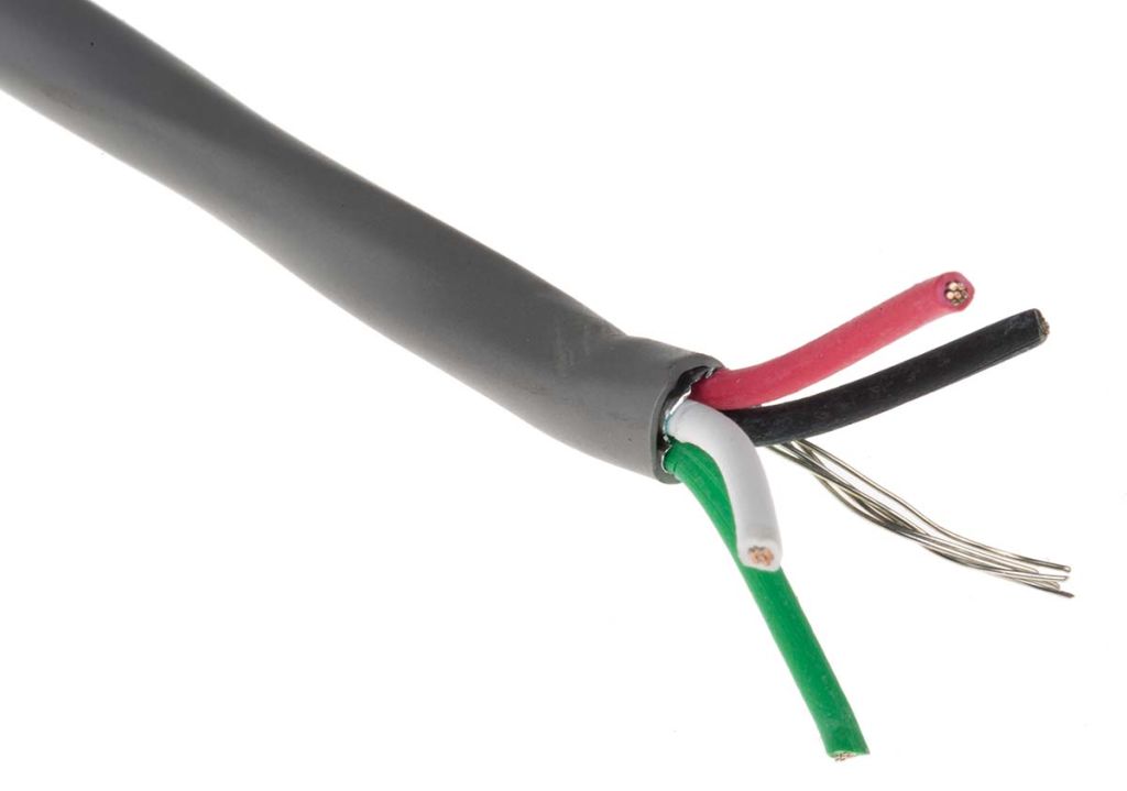
This inevitably sets up a power wrestle the place your Smart Tv gets lonely and needs attention. Does it matter if the shield will get shorted to floor on the host aspect versus the device side? If terminating the shield at each sides is required for high-frequency shielding, while terminating the shield at one aspect is required for low-frequency analog systems to keep away from mains hum. Most copper between the two areas are removed, only a small bridge is used to attach both planes, permitting excessive-frequency alerts to flow on high of the bridge without crossing a slot within the plane, while providing a level of isolation between the circuit ground of chassis floor. Unfortunately, I utterly ignored the problem of another associated question: the connection between the shields and the circuit grounds. Terminating the shield to the chassis, as an alternative of the circuit floor, somewhat mitigates but does not resolve the problem of the lack of RF shielding. For the perfect technique to work, each sides of the shield have to be designed correctly, with the proper bonding of circuit floor, chassis, and shield.
Terminate the shield at chassis on each ends, never the circuit floor. Establishing a low-impedance connection between the circuit ground and the chassis in the I/O space is also advantageous with respect to radio frequency (rf) immunity. Sometimes designers merely have no management over the I/O area. The AV receiver business has been surprisingly unambitious about capturing Platform Revenue, probably as a result of soundbars have pretty much eradicated all the pieces but increased-end, "audiophile"-targeted brands. Coincidentally, this drawback also occurs at a much higher scale in industrial installations across buildings where a significant distinction of "Earth" potential between locations exist. The traditional downside is the 50/60 Hz mains hum in audio. This sacrifices effective RF shielding, lowering the Faraday cage that is capable of blocking excessive-frequency radiation to a easy electrostatic display, solely capable of blocking low-frequency electric fields, like mains hum. Use a triaxial cable with two layers of shields, one is linked at one end for low-frequency shielding, another is related at each ends for RF shielding.

The connection of the shield is subjected to a number of and infrequently contradictory requirements: (1) effective RF shielding, (2) avoiding floor loops that trigger low-frequency noise and hum, (3) ESD immunity, (4) radiation on account of widespread-mode current flowing throughout the shield or chassis. However, for low-frequency purposes, the conflicting requirement of avoiding ground loops mandates that the shield should only be connected at one facet. Consider a cable shield as an extension of the shielded enclosure. The voltage driving the antenna is the widespread-mode voltage between the cable and the chassis. This necessarily mandates the termination of shield and chassis at each sides. Why am I now discussing the connection from shield to the circuit floor? Because the shield is already related to the chassis, the problem of whether the shield should be linked to the circuit ground can be implied right here. Thus, the shield for the twisted pair may be devoted for low-frequency shielding only, and still offering acceptable EMI/EMC efficiency. Unfortunately, for low-frequency or analog techniques, the low-degree noise may cause severe interference. Unfortunately, actual circuit boards have external cables connected, and one of many cable may attach the circuit ground to an external floor, presumably an Earth floor.
But when a circuit board will not be following the assumption behind this methodology to begin with (not having partitioned sections), shield control cable splitting the bottom plane may actually enhance efficiency - an obvious contradiction. CEC right here is an under-the-hood implementation element, one thing that happens behind the scenes to make your soundbar do the few issues it does. For prime-speed RF and digital techniques, that is normally considered to be a suitable price - functional RF shielding is much more essential than just a few millivolts of negligible noise, which is beneath the logic threshold or will be filtered out. See energy off for more details. Connect other non-shield conductors (comparable to energy, sign, energy ground, sign floor) to the circuit, as standard. At low frequency, shields on multiconductor cables where the shield is not the signal return conductor are sometimes grounded at only one finish. This requires the usage of awkward and non-normal cables and is unpopular at present. Thus, it must be thought-about on a case-by-case basis, and it's a non-normal solution.

댓글목록0
댓글 포인트 안내